 |
| Figure 1: Crashed Ariplane |
Thursday, May 30, 2013
Week 9, May 26 - June 1
This week we did some testing of the plane and held a steady hover after fixing some minor flaws from the week before. Specifically the battery was held securely and the pitch gyro sensitivity was reduced. Previously the pitch gyro was over correcting the hover. As can be seen in the video, the plane was capable of holding a steady hover while in helicopter mode. The plane was also tested in for its abilities as a VTOL and unfortunate it crashed. The damage from the crash can be seen in Figure 1. The nose will be rebuilt and it will be tested again this upcoming week.
Thursday, May 23, 2013
Week 8, May 19-25
Monday, May 20, 2013
Week 7, May 12-18
 |
| Figure 1: Wing with Electronics |
 |
| Figure 2: Left Propeller |
 |
| Figure 3: Right Propeller |
 |
| Figure 4: Underneath the Center of the Wing |
 |
| Figure 5: Bottom view of the Wing |
 |
| Figure 6: The Fuselage and Wing |
Thursday, May 9, 2013
Week 6: May 5 - May 11
 |
| Figure 1: Wing Rib |
 |
| Figure 2: Ribs with holes |
 |
| Figure 3: Ribs on the Wing |
 |
| Figure 4: Ribs on the Wing: Top View |
 |
| Figure 5: Complete Wing |
The tail wing was fabricated the same way as the main wing except with less ribs. It can be seen in Figure 6. In Figure 7, the tail wing is shown complete with its wings covered. This covers the work that was completed up to May 9th.
 |
| Figure 7: Tail Wing Complete |
 |
| Figure 6: Tail Wing |
Thursday, May 2, 2013
Week 5 Post April 21-May 4
Today the group worked on cutting out the pieces of the wings for assembly. The wings will be made of three different types of pieces, the top and bottom parts that will enclose the ribs which will give the wings a depth. As seen in Figure 1, the depth of the wing will allow for a great lift while the airplane flies in plane mode. The small bar the is going through the wing is a carbon fiber rod that will turn the motors after the airplane takes off vertically and when required to land vertically. The electronics and servos will be placed inside the plane which will be hallow. The wings were completely cut out and are ready to be glued together. The last things needed to be cut out are the main piece that will hold the two fuselages together, and the tail wings. Once these are all cut out, It will be glued together and the motors will be ready to be attached.
The plane body was cut out, and part of the electrical was completed today. The rotors were connected to their circuit boards by having their wires soldered together. In Figure 2, one of the motors in being soldered to its board with a soldering iron. This completes the work that was performed on Thursday.
 | |
| Figure 1: Remodeled Creo Design with Rotors |
 |
| Figure 2: Soldering the Rotor to its Circuit Board |
Wednesday, May 1, 2013
 |
| Figure 1:Fuselage Being Cut Out |
In Figure 1, the fuselage drawing that was drawn in CAD was printed out on a drafting printer and placed on the foam to make the cuts more precise. The foam was cut with an exacto knife, and two fuselages were cut out. These two fuselages are 24" and will have a piece of foam, 2" wide placed between them that will give a space for the circuit board, battery, and other electronics. Figure 2 shows the fuselage almost completely cut out. In Figure 3, the fuselage is cut out and ready to be assembled. The foam proved to very stable and allowed for accurate cuts without any problems.
 |
| Figure 2: Cutting the Fuselage |
 |
| Figure 3:Main Fuselage |
Saturday, April 27, 2013
Week 4 April 21-27
This week we brought in the foam and had the CAD drawing printed out to scale in order to cut the plane out accordingly.
The foam is 10"X30" and fuselage will be 22". The wings will also be cut out and have a wing span of 18". These will be cut out and glued together. The team is working on cutting it out. To prep for it, the drawings from last week will be printed out in order to be used as stencils on the foam.
In the mean time, research was also conducted on trying to discover how to have the plane hover evenly while the rotors are vertical. The KKmulticontroller v.5.5 “Blackboard”
The Multicopter Flight Controller was found to be the best piece to use. It will be able to keep the plane in a stable while hovering in order to keep it from flying in an unordered fashion. This board can control anywhere from 2 to 6 rotors with the simple purpose of stabilizing the aircraft while flying. It performs this action by taking signals from three different gyros and reads it on its integrated circuit board which processes the information and then sends out a control signal to the Electronic Speed Controllers which are attached to both the board and the motors. Depending on the signal from circuit board, the electronic speed controllers will either speed the motors up for slow them down in order to keep the aircraft level. Along with keeping the aircraft in a steady flight, it will also allow the aircraft to move forwards, backwards, left, right, up, and down. This piece of technology will prove to be most helpful when engineering this airplane.
 |
| Foam for Main Body |
 |
| KKmulticontroller v.5.5 |
In the mean time, research was also conducted on trying to discover how to have the plane hover evenly while the rotors are vertical. The KKmulticontroller v.5.5 “Blackboard”
The Multicopter Flight Controller was found to be the best piece to use. It will be able to keep the plane in a stable while hovering in order to keep it from flying in an unordered fashion. This board can control anywhere from 2 to 6 rotors with the simple purpose of stabilizing the aircraft while flying. It performs this action by taking signals from three different gyros and reads it on its integrated circuit board which processes the information and then sends out a control signal to the Electronic Speed Controllers which are attached to both the board and the motors. Depending on the signal from circuit board, the electronic speed controllers will either speed the motors up for slow them down in order to keep the aircraft level. Along with keeping the aircraft in a steady flight, it will also allow the aircraft to move forwards, backwards, left, right, up, and down. This piece of technology will prove to be most helpful when engineering this airplane.
Thursday, April 18, 2013
Week 3 post April 14-20
 |
| Figure 1: BVertol Ofsprey |
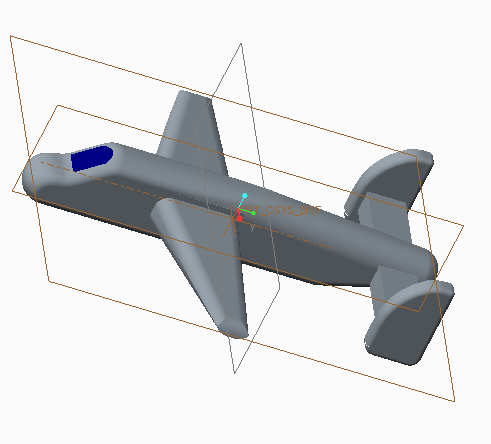 |
| Figure 2: Creo Model of Airplane |
 |
| Figure 3: Creo Model of Airplane |
In Figure 2 and figure 3, a model was created in Creo Parametrics 1.0 to give a rough 3-D sketch of the airplane. It does not have its propellers or motors on it yet as they are still being worked on. Figure 4 is a CAD drawing which can be read by a laser foam cutter that can be used to cut the plane out without and human work. These drawings will prove to be valuable as the team receives all the materials and can begin fabrication.
The team also did research to find out all the required materials and found that they would need the following; Propellers - provides thrust required to move the airplane Propeller Adapters - fastens propellers to the motor Carbon Fiber Rod - gives strength to the airplane's wings Foam - the substance the airplane is composed of Battery - a source of power for all electronics Servos - provide movement to all control surfaces Motors - provide thrust to give the airplane flight Electronic speed controllers(ESC's) - regulates the motor's electricity consumption 3-Axis flight stabilizer - stabilizes the airplane's movement while hovering.
 |
| Figure 4: CAD model for laser cutting |
These parts were all ordered from hobbyking.com and valuehobby.com. The total cost came to $130 split between the five members. This is all the research and work that was performed with week and the group hopes to start building next week.
Thursday, April 11, 2013
Second Week, April 7-14, Sketching and Dimension
Week 2
Today we started talking about the basics of the plane and how the plane will operate. We did some research on how the making of the plane is possible. We looked up forums of other people who have created them before in order to get an idea of weight distribution and sizing. We found this forum extremely helpful, http://www.rcgroups.com/forums/showthread.php?t=1496110. We decided that the airplane have a wingspan of 18' x 3.5' with an area of 63.5 cube inches. Then we continued to look into the different weights of the plane and how to distribute it correctly. We will be using foam for the main frame of the plane, and the motors may be supported by a carbon fiber bar that spans across the wings. Some plans will be drawn up on how to cut the foam, and a laser cutter may be used to cut out the foam, otherwise it will be cut out by hand. We planned to meet at least twice a week outside of class in order to work on the robot. This is all we covered during this meeting.
Today we started talking about the basics of the plane and how the plane will operate. We did some research on how the making of the plane is possible. We looked up forums of other people who have created them before in order to get an idea of weight distribution and sizing. We found this forum extremely helpful, http://www.rcgroups.com/forums/showthread.php?t=1496110. We decided that the airplane have a wingspan of 18' x 3.5' with an area of 63.5 cube inches. Then we continued to look into the different weights of the plane and how to distribute it correctly. We will be using foam for the main frame of the plane, and the motors may be supported by a carbon fiber bar that spans across the wings. Some plans will be drawn up on how to cut the foam, and a laser cutter may be used to cut out the foam, otherwise it will be cut out by hand. We planned to meet at least twice a week outside of class in order to work on the robot. This is all we covered during this meeting.
Wednesday, April 10, 2013
Week 1, March 31 - April 6, Ideas
During the first week we were introduced with a project of recreating a wind turbine to conduct electricity. The group decided they did not want to fabricate that, but instead came up with other ideas. The group decided on a Model VTOL (Vertical Take Off and Landing) airplane. These model planes are not currently on the market for purchasing and only a few people have attempted to create them. The group saw this as an opportunity to create a model airplane that was not so simple to create. They brainstormed and came up with the idea. Mark Petro-Roy will be leading the group, as he has a strong foundation in replicating model airplanes. The group went to work in the first week to look into ordering the necessary parts and laying out a plan and timeline of when they will finish their major tasks. This concluded the works of week one.
Subscribe to:
Comments (Atom)